Sunday, August 13, 2017

When things go horribly wrong with your 3D printer

I've been printing a lot of parts lately. My printer (an Anet A8 w/ mods) has been quite reliable using my process. My process involves printing on glass, w/ Elmer's glue stick on the surface (more about that later).
I have IPWebcam running on an old cell phone so I can monitor the printer from upstairs or outside of the house. I had started a print with a fairly full build platform and checked it before going to bed. I saw one corner didn't look quite right, but I was tired and thought I'd sort that out in the morning. Big mistake! Here's what I woke up to:
Oh, and this was on the floor:
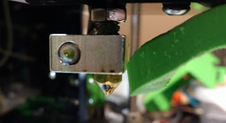
OK, I'm sure this is fixable. Well, not the glass, but I got that for free, so I'm sure I can get more. I need to clean off that hot end though! Chipping it off isn't an option.. way too difficult. I raised the Z and moved the X over the center of the build platform to give me some space to work. I turned up the extruder temp to 200 degrees C. As it reached that temp, I could wiggle that mass. I was able to get it tilted off the hot end and then carefully pulled the heating element out by grabbing the cooler part of the wire further away from the element. Now, I had to shut off the heat because when it's not in the block, you get thermal runaway as the thermistor can't tell it's already hot enough.
While things were still hot, I grabbed a heavy shop paper towel and folded it over a couple of times. I could drag that across the heat block and extruder tip. It picked up all of the melted PLA after several tries. Be careful to not wipe the hot end with your fingers behind the paper towel. Hold a longer piece between your 2 hands and rub it over the PLA on the hot end so it drags the plastic off.
I cleaned the heating element and as much of the thermistor in much the same way. I was able to heat it up again and re-insert it to re-heat the hot end when I wanted to get more PLA off. I was also able to get the paper towel in above the heat block and clean off the threaded tube.
I found the block was loose and so, I used some pliers to carefully twist it tight again. That threaded tube is not super strong, so don't torque it too much! I cleaned out the hole where the heating element went and reinserted the element. In the past, I had a single layer of aluminum foil wrapped on the element so it was pretty snug in the heat block. I did that again and got it all back together. It's looking pretty good now!
The root cause of all of this: One corner of the part had lifted up where I didn't have good glue coverage. It hardened and caused the hot end to crash into it. Not sure where the PLA started globing up, but I assume at some point, part of the part that lifted became stuck to the hot end and started picking up new plastic that was being extruded. It all got very bad from there. It knocked into the binder clips holding the glass, the glass moved (part of a layer was printed at an angle at some point). The glass eventually ended up on the floor, broken. Lesson here, keep an eye on things! Most stuff goes wrong in the first layer. The chance of things going south vastly decreases as the layer count goes up (assuming you have good adhesion and don't run out of filament!).


Monday, May 22, 2017

Shapeoko 3 Work Holding System

What I'm going to describe is so useful, I'm not sure why Carbide3D doesn't offer it out of the box! Our FIRST robotics team decided to purchase a Shapeoko 3 XL to allow us to machine larger parts, but also fit it through doorways in our school. Our team has limited space and needs to pull everything out of a store-room to start working on any project. This version of the Shapeoko has a pretty hefty 3/4" MDF bed that bolts to the steel frame. It came pre-drilled for the M5 socket-head bolts. We saw videos from Winston Moy and others about the finer points of Shapeoko 3 ownership and were especially impressed by the hold-down system he showed for his Shapeoko 2. It involved threaded inserts and slotted wood pieces that were used to hold down material being machined with the help of bolts into the threaded inserts arrayed around the MDF bed. I've linked to the video to help illustrate.

We decided to tackle this and were able to get the insert part # by pausing the video and ordered this from McMaster-Carr. Further reading about these inserts indicated that they would be strongest if we inserted them from the bottom of the MDF. The flange provides additional strength that way so the inserts won't pull out. We wanted to be sure many students on our team would be able to use this machine for years to come, without damaging it.

We had to decide how many inserts to install and how to arrange them on the board. We use SolidWorks for all of our CAD and decided to use the LinearPattern tool to lay out holes in the MDF board. It was a huge help since the starting offset and spacing could be tweaked very easily. We ended up centering the pattern left-to-right (along the machine's X axis) and because of how the Z axis hangs off the front of the X axis gantry, we aren't able to reach the far back of the MDF, so we left a row blank on the back edge. It was easy to generate a dimensioned drawing from SolidWorks which helped when machining the holes.


Next was the hole profile. We had a little trouble generating g-code using the tools Winston used (probably due to lack of experience), so ended up designing the hole profile in SolidWorks and using HSM Xpress to define the tool paths. We chose to use 1/2" inserts in the 3/4" MDF, so there would be some room to level the bed by machining it with a fly cutter.


Since the Shapeoko cannot reach the extents of the bed due to mechanical limitations (except the front edge), we knew we'd need to position the MDF a few different ways to allow the hole pattern to be machined in. We also knew if we were going to machine all the way through, we'd need a waste board underneath to prevent us machining into the steel frame. We also got some 2" M5 bolts to reach from the top of the MDF (which is upside down) through that and the waste board and into the threads in the frame. After securing the MDF by shifting it to overlap the middle set of holes with the existing holes in one end of the MDF, we were ready to start.

Using a ruler, we measured the offset of the 1st hole. This would be the anchor point for the entire grid of holes, so measure carefully! We used an 1/8" flat end-mill to machine our holes. Using Carbide Motion, it's pretty simple to position the bit over the hole. Bring it pretty low over the MDF, adjust X and Y to line up with the marks. We use the paper trick to adjust the Z axis. Drop the Z by small increments while moving paper underneath the bit. Once the paper sticks, raise the Z 1 step, remove the paper and drop the Z back down 1 step. Now, set zero for all axis and you're ready to start!

After running the code for the hole, the bit ends up off-center, so before moving to the next hole, it's a good idea to use reset X-Y (through Carbide Motion). Then, you can jog the machine in either X or Y direction 3 inches to start the next hole. Once the X-Y are set, repeat the Z setting procedure with the paper and reset zero for all axis. Rinse and repeat till you need to reposition the board to reach more holes. Eventually, you'll end up with a board that looks like this.


Pretty slick! Now, you can install that on the machine and use your hold-downs!